Overview
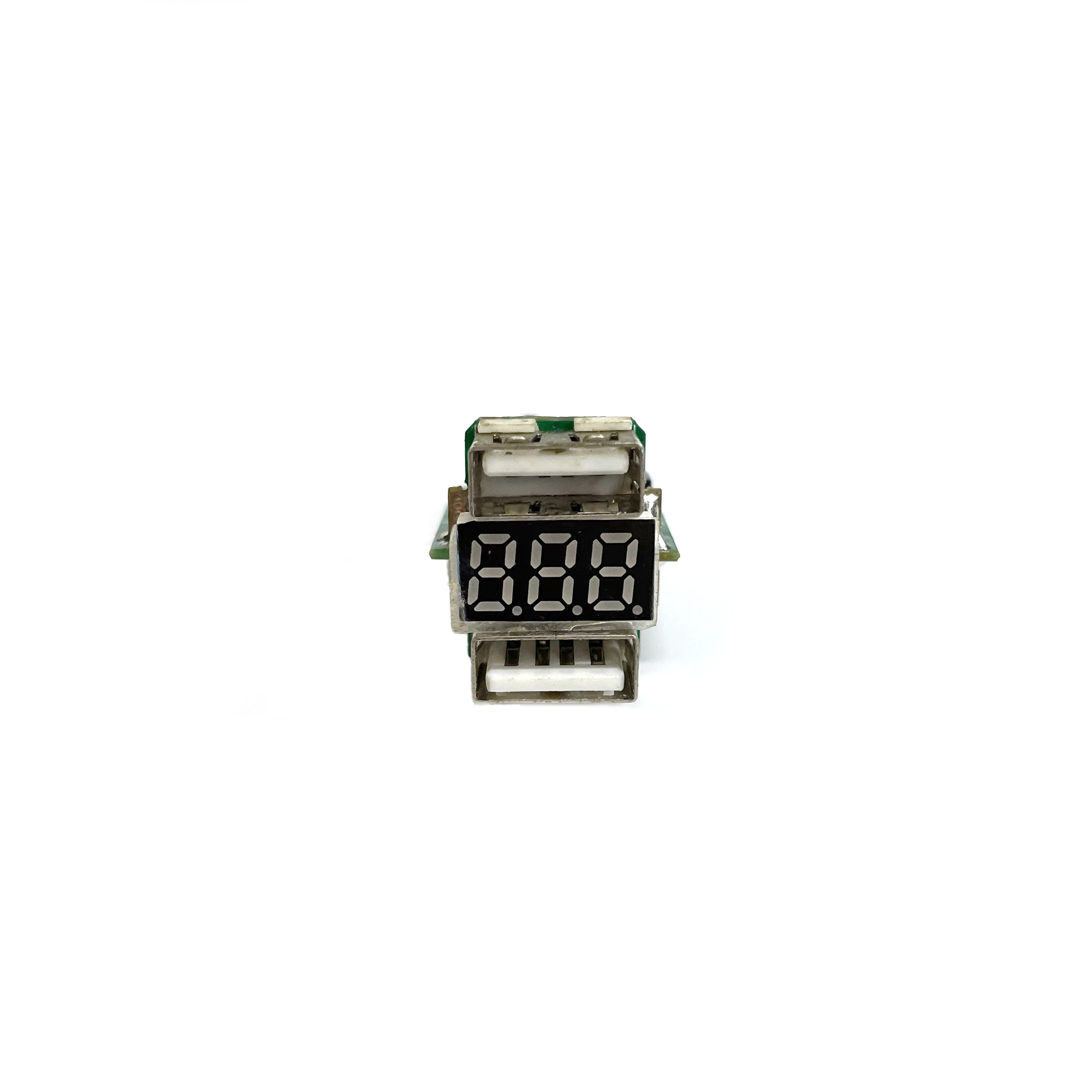
This charger module places a three-digit seven-segment display between two USB-A receptacles. The finished product can show an electrical reading at the same front face used for both charging outputs.
Manufacturing Challenge
The upper port, display, and lower port must meet three separate openings in the enclosure. A tilted display or shifted connector shell can make an electrically sound board unusable. The display pins and connector anchors also require different soldering conditions, so heat exposure and component position have to be controlled together.
Manufacturing Approach
The front-panel datum, decimal-point position, display orientation, and USB spacing are set before production. A fixture holds all three front-facing parts square to the PCB while their solder joints cool. AOI checks the accessible SMT area; visual inspection covers the display pins, shell anchors, coplanarity, and residue. Functional testing exercises every display segment and checks both USB outputs against the product specification.
Result
The two outputs and numeric readout share one narrow module, so no separate display board is needed. The fixture controls the details visible after assembly: the position of both ports and the alignment of the display behind its window.