Overview
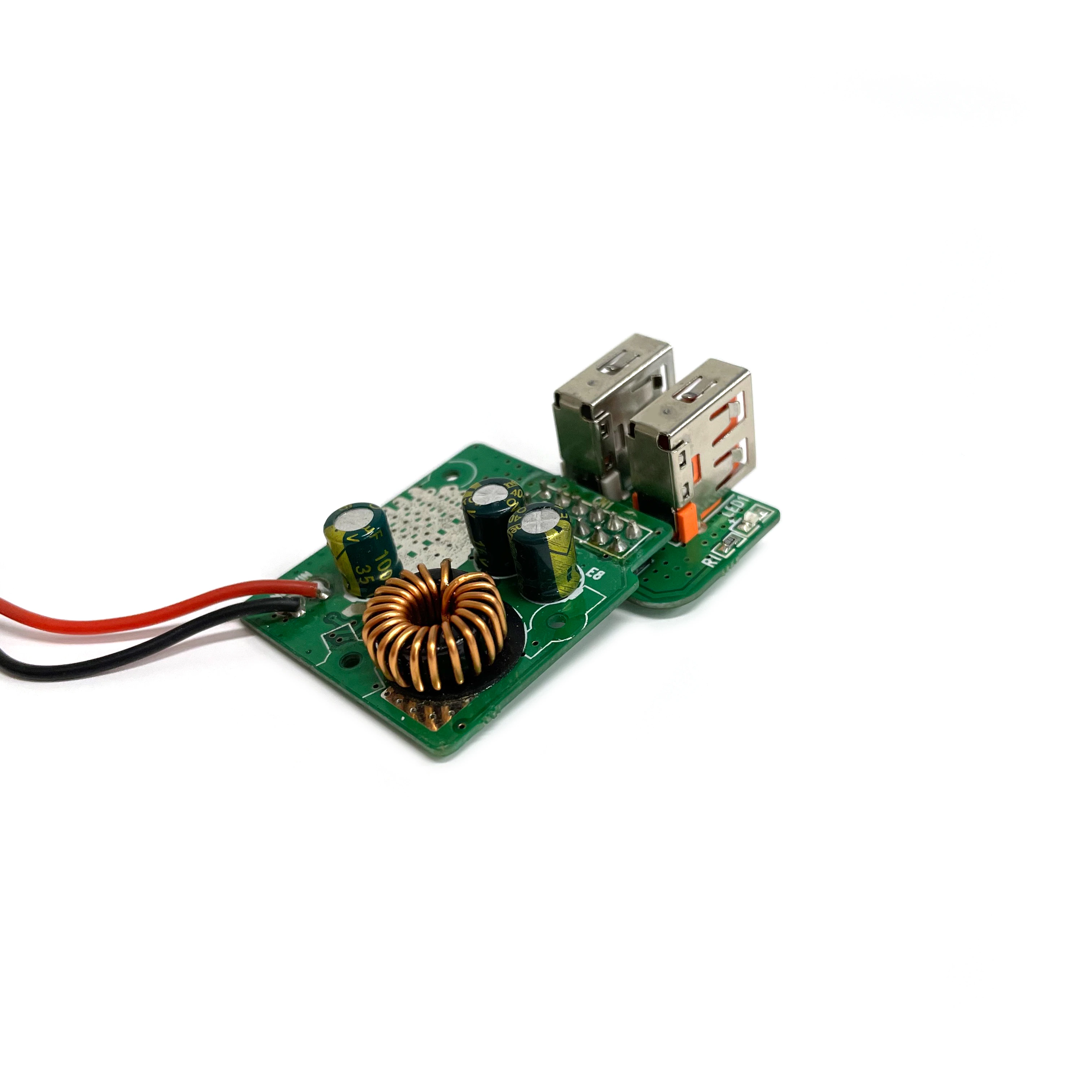
This vehicle-powered USB board uses a broad PCB with two side-by-side USB-A receptacles, a toroidal inductor, electrolytic capacitors, and a wired DC input. The layout is better suited to a panel or larger accessory enclosure than to a plug-shaped charger body.
Manufacturing Challenge
The board has two mechanical interfaces. Both USB ports must match the panel cutout, while the input leads need correct polarity and strain relief. The large inductor and capacitors can move during handling, and their joints require enough heat for proper wetting without disturbing nearby components.
Manufacturing Approach
Connector height, port spacing, and cable exit are checked against the enclosure drawing before assembly. SMT parts are populated first. Fixtures hold the USB receptacles level while the connectors, inductor, capacitors, and input leads are soldered. Inspection covers shell anchors, inductor joints, capacitor polarity, wire preparation, residue, and edge clearance. A load fixture can then test each output independently under the conditions set for the product.
Result
Once assembled, the two USB receptacles face the product panel and draw power through the wired vehicle input. A separate fit check and load test catches port misalignment as well as faults in the power stage before installation.