Overview
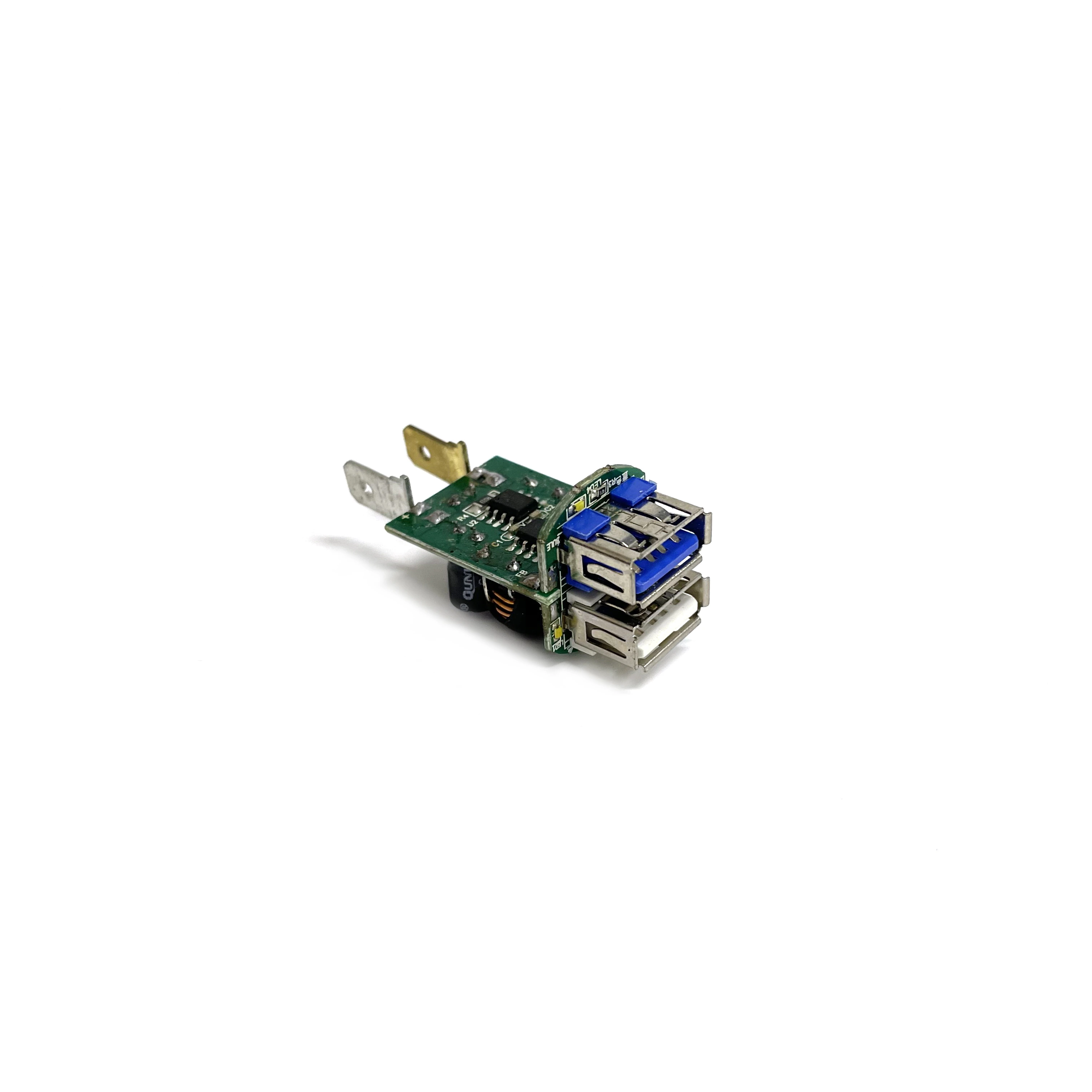
Two stacked USB-A receptacles, a switching stage, metal input contacts, and a separate indicator section are packed into this narrow automotive charger assembly. Its shape suits a plug-style housing, but leaves little tolerance for connector or daughterboard movement.
Manufacturing Challenge
The USB ports must remain parallel to each other and square to the housing opening. At the other end, the input tabs have to meet the enclosure's contact system. A board can pass an electrical check and still fail at final assembly if either interface has shifted. The inductor and electrolytic capacitor add thermal mass, and the indicator board adds another soldered joint between boards.
Manufacturing Approach
Connector datums, finished height, and daughterboard orientation are defined in the assembly drawing. SMT processing comes first. A fixture then holds the USB stack and input contacts while the larger parts are soldered and cooled. Port spacing, shell joints, indicator orientation, contact alignment, and clearance inside the housing are checked before functional testing. When product limits are available, the test fixture can measure output voltage, no-load current, and both ports under load.
Result
Two charging outputs and the indicator fit within the space of a vehicle accessory plug. Holding the mechanical references during soldering addresses enclosure-fit problems before they reach final assembly.