Overview
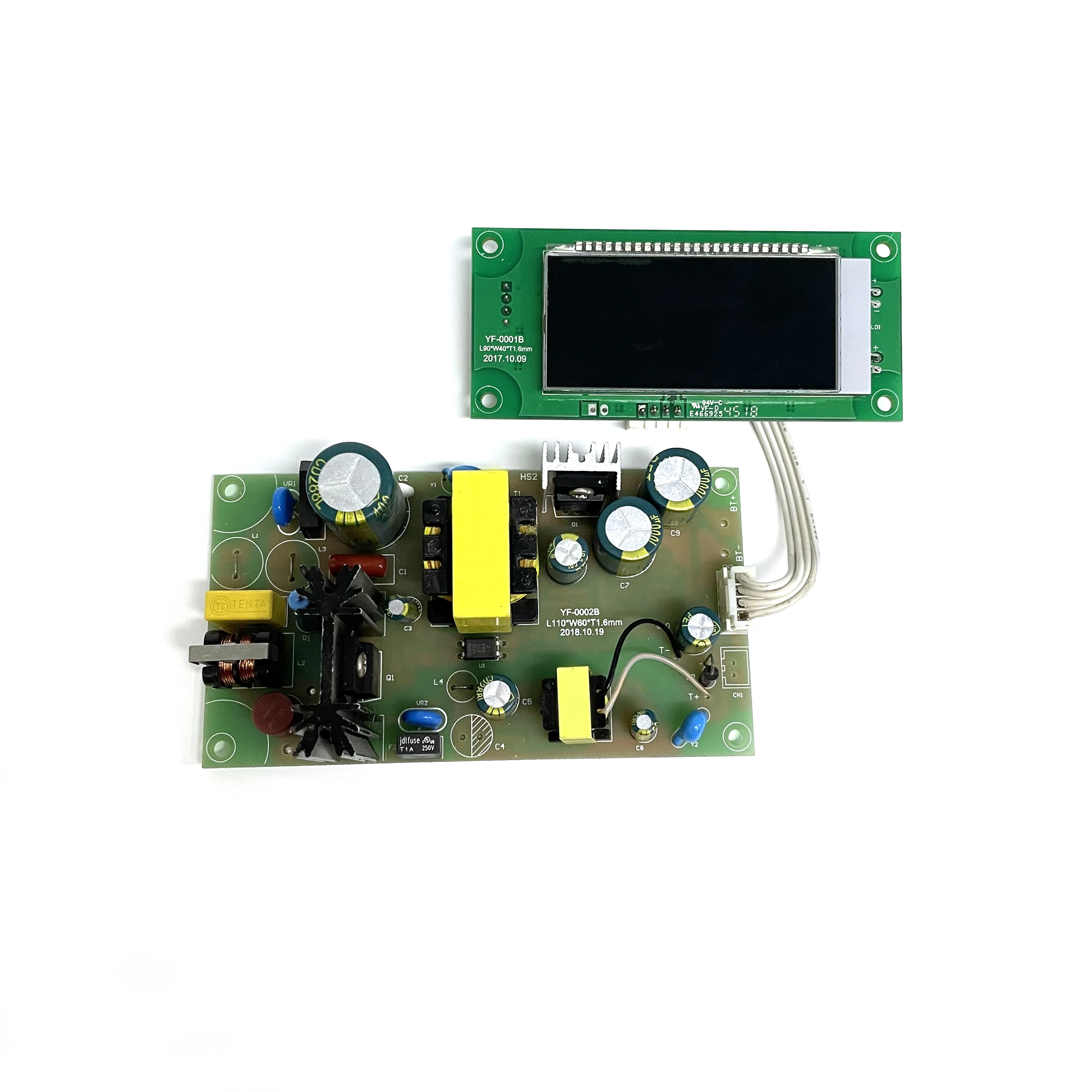
This charger is split between a power-conversion board and a separate LCD module. The main board carries the transformer, filtering, heatsink-mounted devices, connectors, and battery terminals. A cable links operating data to the display, keeping the user interface away from the higher-energy section.
Manufacturing Challenge
Polarized capacitors, wound parts, heatsinks, and temperature-sensing leads each need different handling. The display cable must be routed without pulling on its connector or touching hot components. Test limits also depend on the intended battery chemistry and charging profile; a generic output-voltage check is not enough to validate the assembly.
Manufacturing Approach
Review starts with polarity marks, connector pinout, display cable order, transformer orientation, and the spacing defined by the power design. SMT assembly is completed before the transformer, capacitors, heatsinks, and other larger parts are installed. The cable is secured with a controlled route between the two boards. Inspection covers power joints, fuse position, heatsink hardware, capacitor polarity, connector seating, and display cleanliness. Functional tests follow the approved charging specification and can include current-limited startup, display communication, charge indication, and temperature-input response.
Result
Separating the display from the power board leaves more freedom in the front-panel layout and avoids crowding the higher-energy section. The power path and display connection can also be checked separately before both boards go into the enclosure.