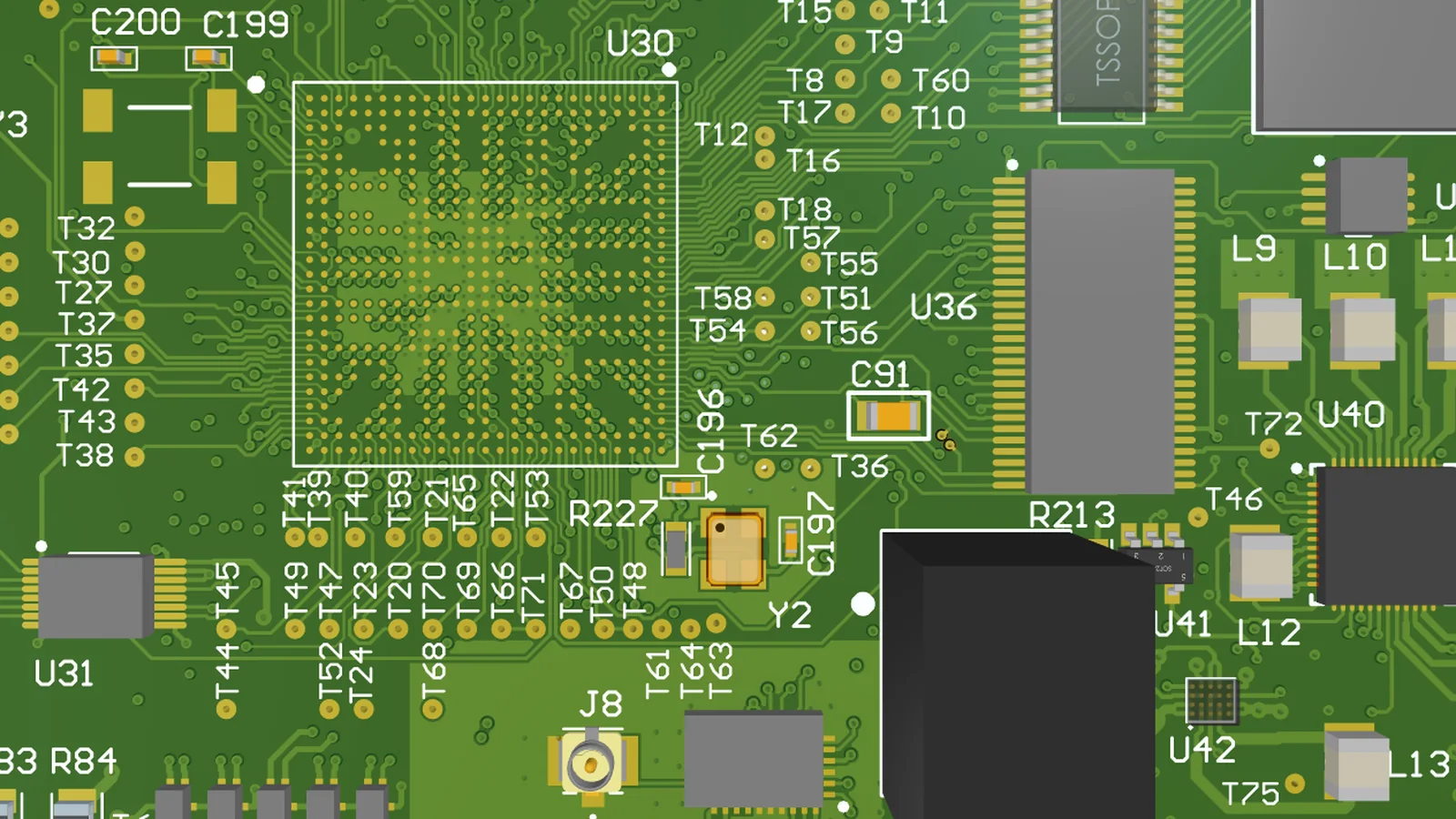
On August 31, 2026, an electronics developer described an unexpected manufacturing problem on Reddit. The developer had already produced and deployed more than 3,000 units of a PCB-based product and had been using the same design in production for approximately three years.
When attempting to move production to PCB manufacturers in Japan, however, the developer encountered a series of engineering questions.
The manufacturers requested clarification about internal copper thickness, silkscreen drawings, component placement, drill locations, V-cut positions, solder mask specifications, and the meaning of DNP.
According to the developer's account in the r/embedded discussion, the exchanges had continued for approximately four months.
The developer maintained that the necessary information was already present in the submitted manufacturing files and questioned why previous suppliers had been able to produce the assemblies without comparable correspondence.
The account is a publicly available first-hand report, not an independently verified investigation of the manufacturers involved. It does not establish that the submitted files were incomplete or that every question was necessary.
It does point to a recurring problem: a PCB design that has already been manufactured successfully does not necessarily come with a data package that another supplier can read without asking questions.
For Original Equipment Manufacturers (OEMs), delays after file submission can affect component purchasing, production scheduling, and delivery commitments. Understanding why those delays occur requires looking beyond the presence of Gerber files and a Bill of Materials (BOM).
Why a Previously Manufactured PCB May Still Require Engineering Clarification
A design that has been manufactured successfully by one supplier may contain manufacturing assumptions that were never formally documented.
The original manufacturer may already know which board material, solder mask, surface finish, panel arrangement, or assembly conditions were used during previous orders.
Some of those decisions may have been established through earlier engineering discussions or stored in the supplier's internal production records.
When production moves to another factory, that information does not necessarily travel with the Gerber files.
A new manufacturer must determine whether the available documentation adequately defines the product and whether the design can be manufactured within its own process capabilities.
Not every request for clarification indicates a missing specification, though.
A manufacturer might ask for information that is already present in a drawing or machine-readable file because its internal review process has not recognized it. Different CAM systems and document-handling workflows can also create unnecessary manual interpretation.
In the August 2026 Reddit discussion, the developer reported supplying Altium design files, a BOM, pick-and-place data, and drawings containing several of the details being requested.
Other participants questioned whether certain manufacturing conditions, such as soldering materials or panel fiducials, had been sufficiently defined.
The available discussion does not conclusively establish which party was responsible for the prolonged exchange.
For an OEM, the practical aim is a documented set of requirements clear enough that the supplier can name exactly what remains unresolved before the order goes to production.
Gerber Files Describe the PCB, Not the Complete Assembly
Gerber is widely used to transfer PCB fabrication data, including copper patterns, solder mask, and silkscreen artwork.

But the information needed to manufacture a bare PCB differs from the information needed to populate it with electronic components.
Ucamco, the organization responsible for maintaining the Gerber format, explains that Gerber X2 adds standardized attributes that identify layer functions, polarity, pad functions, and other design information.
These attributes help CAM systems interpret fabrication data more reliably.
Ucamco also explains in its Gerber Job documentation that PCB manufacturing requires information beyond layer artwork, including board thickness, material specifications, and surface finish.
The Gerber Job format provides a method of conveying such fabrication information in machine-readable form.
This distinction matters when a manufacturer receives only individual artwork files without sufficient accompanying specifications.
For example, copper layers may describe the electrical routing, but the intended dielectric construction, board thickness tolerance, controlled-impedance requirements, or surface finish may still require separate definition.
A PCB fabricator must also understand the intended finished board outline, drill characteristics, and any special fabrication instructions.
These are not necessarily design defects. They may be specifications required to distinguish the intended finished product from the geometric patterns in the artwork.
Assembly introduces further information requirements.
A fabricator can produce a bare PCB without necessarily knowing which component should be mounted at each reference designator. An assembly provider must know which components to install, their intended locations and orientations, and any special process requirements.
In its PCB Assembly Outputs guidance, published in July 2026, Altium explains that the manufacturing package must communicate not just component identities but also assembly instructions and design intent.
A complete handoff therefore involves distinguishing fabrication information from assembly information while ensuring the two describe the same approved product.
Why the BOM and Pick-and-Place File Must Agree
A BOM identifies the components required for assembly and associates them with reference designators on the PCB.
A pick-and-place file, sometimes called a Component Placement List (CPL) or centroid file, describes where components should be positioned.
These files have related but different purposes.
The BOM supports component identification and purchasing. Placement data supports machine programming and component positioning.
According to KiCad's official PCB Editor documentation, component placement outputs contain footprint positions and orientations. Designers can also control whether certain footprints, including components marked Do Not Populate (DNP), appear in the exported placement data.
That flexibility is useful, but it introduces a potential source of disagreement between manufacturing files.
Consider a PCB design containing an optional communication interface.
The schematic and PCB layout may include the interface components, while the specific product variant being ordered does not require those parts to be installed.
If the BOM identifies them as DNP but the placement file was generated using a different configuration, the two files may describe different assembly requirements.
The manufacturer then needs to determine which configuration is intended.
The same issue can arise when a PCB revision introduces a new component location but the placement file comes from an earlier design export.
Altium's October 2026 guidance on simplifying PCB output generation explicitly addresses such inconsistencies.
It describes situations in which a revised Gerber package is accompanied by an older drill drawing, or a BOM represents a different assembly variant from the placement file.
No single file is necessarily unreadable. The problem is that together they fail to define one consistent manufacturing configuration.
For an OEM, this makes the approved assembly variant as important as the correctness of each individual document.
The design owner should be able to identify which components must be installed, which positions must remain unpopulated, and whether alternative components or assembly configurations are permitted.
If that information is unclear, the manufacturer should request confirmation instead of deciding independently which version is correct.
A Real Assembly Preview Case: One Component Rotated 180 Degrees
Another publicly documented case illustrates why correct-looking design files do not always produce an immediately acceptable assembly preview.
On March 8, 2026, a user posted in r/AskElectronics about a PCB assembly order.
The user had submitted Gerber files, a BOM, and pick-and-place information to JLCPCB.
After receiving an assembly preview, the user noticed that a transistor appeared to overlap an unexpected solder pad and questioned whether the problem originated in the design or the assembly preparation.
The user also reported that the PCB design had passed its design rule check.
Several participants examining the preview identified a possible 180-degree component rotation. During the discussion, the original poster subsequently acknowledged that the component was indeed rotated 180 degrees.
The public discussion does not establish that incorrect boards were ultimately manufactured or that the supplier was responsible for the initial orientation discrepancy.
What it demonstrates is the value of reviewing the proposed component placement before production begins.
Component rotation is not always interpreted identically across design libraries and manufacturing systems.
JLCPCB's PCB Assembly FAQ, updated in September 2026, explains that a design library's zero-degree orientation may differ from the convention used by its placement workflow.
Its documentation describes how a component may appear in an unexpected orientation during preview and how the placement data or engineering review can resolve the difference.
For polarized components, pin assignments and orientation are particularly important.
A placement file may contain a numeric rotation that is internally valid, while the manufacturer still needs to confirm that the physical component matches the intended pad and pin arrangement.
This is why an assembly drawing can provide information that complements machine-generated placement data.
Altium's assembly documentation guidance identifies reference designators, component orientation, polarity, mounting details, and special process instructions as relevant elements of assembly documentation.
Component rotation is not always a design error, but placement data, footprint definitions, actual packages, and assembly previews should be checked against the same approved design.
A question raised during this review can prevent an incorrect interpretation from reaching production.
Passing DRC Does Not Mean the Board Is Ready for Every Manufacturing Process
Design Rule Checking (DRC) is a standard part of PCB design verification.
It can identify violations against the constraints configured in the electronic design automation software, such as certain clearance, connectivity, or geometric rules.
However, DRC does not automatically verify every condition involved in manufacturing and assembling a particular board.
A design may satisfy its configured clearance requirements while still presenting challenges for a specific production process.
Examples include component access during assembly, panel handling, solder paste deposition, or manufacturing features that depend on a supplier's equipment and process limits.
A design may also require specialized board materials, surface finishes, or inspection conditions that have not been fully communicated through the exported artwork.
This is where Design for Manufacturability (DFM) and Design for Assembly (DFA) reviews become relevant.
These reviews assess the submitted design against the capabilities and intended processes of the manufacturer.
The distinction is consistent with Altium's guidance on preparing a design for manufacture, which separates design rule validation from the generation and review of fabrication and assembly outputs.
A useful manufacturing review should produce specific findings rather than broad statements that a design is not ready.
For example, the manufacturer may identify a conflict between the requested board construction and its available fabrication process, or a component placement that requires additional confirmation before automated assembly.
Some issues can be resolved through established manufacturing methods without changing the customer's approved electrical design.
Others require a design modification or explicit approval from the OEM.
The appropriate response depends on the nature of the issue.
Treating every question as evidence of poor design can be misleading. Equally, a manufacturer should not repeatedly request information already provided without identifying what remains technically unresolved.
A productive DFM review explains the concern, identifies its relationship to the intended manufacturing process, and makes clear whether a technical decision is required from the design owner.
When Manufacturing Questions Require Customer Approval
Engineering questions generated during manufacturing review do not all have the same significance.
Some concern missing documentation. Others involve interpreting supplied information or proposing a change to the approved product.
For example, a manufacturer may need confirmation of an unspecified surface finish before it can finalize fabrication planning.
That differs from proposing a change to the PCB's copper geometry or replacing a component with an alternative part number.
The latter may affect the product's approved electrical or mechanical configuration.
The authority to make such decisions should be defined before the manufacturing process begins.
Industry work on IPC-2581, an open standard for exchanging PCB manufacturing information, addresses the same problem of keeping exchanged data consistent.
A March 2026 article in Printed Circuit Engineering Association Magazine, contributed from the IPC-2581 community, describes how structured data can improve communication between designers and manufacturers, including the exchange of design-for-manufacturing findings and technical questions.
That article promotes IPC-2581 and should be understood as an industry participant's technical perspective, not independent proof that a particular file format eliminates manufacturing delays.
Its underlying concern is nevertheless relevant: information exchanged through disconnected documents, spreadsheets, and email threads can be harder to keep consistent.
For an OEM project, engineering queries are more useful when each question identifies the affected design feature or document, explains the manufacturing concern, and states what information or approval is required.
Where a modification is proposed, the corresponding design revision and production instructions should be updated after approval.
A supplier should not treat an unanswered design question as authorization to change the customer's product.
Likewise, the design owner should not assume that every manufacturing interpretation can be made safely without review.
The objective is to distinguish routine manufacturing preparation from changes that affect the approved product.
Why File Revisions Can Create Delays Even After Engineering Approval
A manufacturing data package can become inconsistent after a seemingly minor design update.
For example, an OEM may approve a different connector during a component availability review.
The revised BOM may reflect the new part number, but the assembly drawing or placement data may still refer to the original package.
If the replacement has different physical dimensions, the manufacturer needs confirmation that the PCB footprint remains suitable.
Alternatively, a PCB layout change may be incorporated into the Gerber outputs while the drill files or fabrication drawing remain unchanged.
These examples describe possible configuration mismatches, not specific manufacturing incidents.
The risk is that different documents can appear individually correct while referring to different product revisions.
Altium's Design Project Release documentation describes how fabrication and assembly data can be released and managed as defined project revisions.
It distinguishes fabrication outputs from assembly outputs and supports separate assembly data for different product variants.
That approach meets a basic requirement: the supplier needs a consistent, identifiable set of files that represents the intended product release.
For OEMs managing repeat orders, this becomes especially significant when multiple engineering revisions or product variants are active.
A previously approved design should not be assumed to apply automatically to a newly submitted order if the BOM, PCB artwork, or assembly requirements have changed.
The manufacturing package should identify the applicable revision and configuration. When a new revision is approved, affected outputs should be regenerated and checked together.
None of this is paperwork for its own sake.
A clear release configuration helps the manufacturer determine which files are valid for purchasing, bare-board fabrication, machine programming, inspection, and final product verification.
Does Every Engineering Question Mean the Delivery Date Will Be Delayed?
A request for clarification does not necessarily delay production.
The effect depends on the issue, when it is discovered, and whether manufacturing activities can proceed safely while the question remains open.
Some questions can be resolved during quotation or preliminary DFM review without affecting the planned production start.
Others may prevent the manufacturer from purchasing a critical component, preparing production data, fabricating the bare PCB, or releasing the assembly to the production line.
For example, an unresolved component substitution may prevent procurement if the proposed alternative requires customer approval.
An unclear board construction may prevent fabrication planning from being finalized.
An uncertain component orientation may need to be resolved before placement data is released for assembly.
The effect on scheduling is therefore linked to the manufacturing operation that depends on the missing decision.
This distinction also explains why an advertised assembly turnaround time should not automatically be interpreted as the time between the customer's first file upload and shipment.
Manufacturers may require completion of engineering review, acceptance of the manufacturing data, component availability confirmation, or other order-specific conditions before the relevant production schedule can be finalized.
An OEM evaluating delivery commitments should ask which manufacturing activities have actually been released and which remain dependent on engineering or purchasing decisions.
A project waiting for confirmation of a component package is in a different condition from one whose approved materials have already been received and prepared for assembly.
Accurate scheduling depends on distinguishing these states rather than treating file submission as equivalent to production readiness.
How OEMs Can Reduce Delays Before PCB Assembly Begins
Producing more documents rarely helps on its own. What does help is a coherent manufacturing package that defines the intended product and makes unresolved requirements visible before production commitments are finalized.
For a typical PCBA project, fabrication information may include the PCB artwork, drill data, board construction, fabrication notes, and any applicable mechanical or special process requirements.
Assembly information may include the approved BOM, component placement data, assembly drawings, product variants, and special handling or testing instructions.
The exact requirements depend on the design and the services being purchased.
A manufacturer providing both bare-board fabrication and component assembly may review these requirements as part of an integrated process. Where the work is divided between different suppliers, the documentation and responsibility boundaries become more important.
The OEM should also establish which party is authorized to approve component alternatives, adjust assembly requirements, or release engineering changes.
A clear revision identifier helps ensure that the files reviewed by engineering are the same files subsequently used by procurement and production.
When the manufacturing review identifies a question, the supplier should be able to explain what is missing or inconsistent and whether the issue affects quotation, purchasing, fabrication, or assembly.
The customer can then provide the specific clarification or authorization needed.
This approach does not guarantee that every order will proceed without additional questions. Complex boards, unusual components, and specialized manufacturing requirements may still require technical coordination.
But it reduces the likelihood that avoidable file discrepancies will be discovered only after procurement or manufacturing preparation has begun.
A Successful File Submission Is Not the Same as Production Readiness
The August 2026 Reddit discussion illustrates how an established PCB product can encounter unexpected engineering questions when manufacturing arrangements change.
The March 2026 assembly-preview case demonstrates a different issue: a design that has passed its configured DRC checks may still require confirmation of component orientation before production.
Neither case proves that manufacturing review is inherently inefficient or that the design owner is always responsible for a delay.
They show why the manufacturing handoff deserves its own attention.
Gerber data, BOMs, pick-and-place files, fabrication specifications, and assembly instructions serve different purposes. Their presence in a folder does not automatically demonstrate that they define a consistent, approved manufacturing configuration.
For OEMs, the objective is to ensure that the manufacturer can identify the intended product, evaluate its production requirements, and distinguish routine process decisions from changes requiring customer approval.
Tongyong Industries supports PCB fabrication, component sourcing, SMT and through-hole assembly, DFM review, and PCBA testing.
Through its PCB assembly services, OEM customers can submit available Gerber files, BOMs, assembly documentation, and project requirements for an initial engineering and manufacturing review.
Identifying missing information, conflicting revisions, and manufacturing constraints before production release provides a more reliable starting point for PCB assembly planning and delivery coordination.