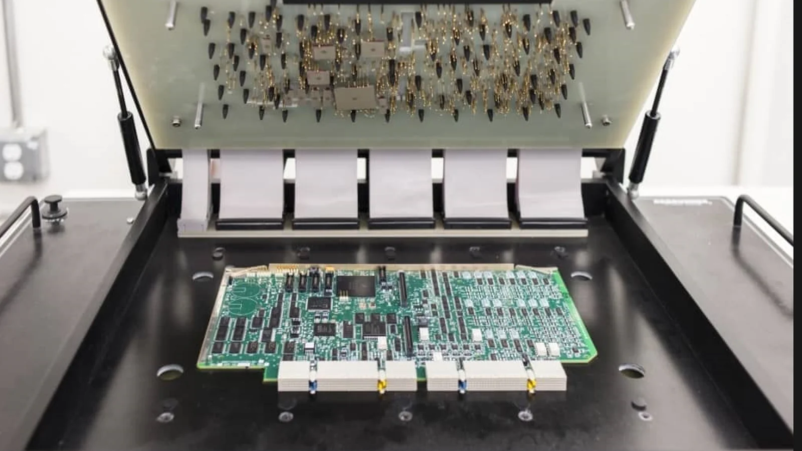
In January 2026, an engineer raised a manufacturing test question on Analog Devices' official EngineerZone forum. During in-circuit testing (ICT) of PCB assemblies containing the ADSP-21565 digital signal processor, some device pins produced unexpected diode, resistance, and capacitance measurements.
The engineer reported that replacing the processor on the same board eliminated one of the observed measurement anomalies. The question was whether those results indicated defective components or limitations in the test method.
On February 9, 2026, Analog Devices responded through its engineering support team.
The company explained that applying component-level electrical measurements to a complex processor installed on a PCB can produce results that are difficult to interpret. It also noted that its relevant pin tests checked for open and short circuits rather than specific impedance values, because the latter were not specified for those pins.
In the public technical discussion, Analog Devices distinguished between the semiconductor's own production testing, PCB fabrication continuity checks, and power-on self-tests performed on assembled evaluation boards.
The exchange does not establish that the processors were defective. It points to something more relevant to PCB assembly quality control: a test result can sit outside an expected range without proving that the tested component or assembly is faulty.
The opposite problem is also possible. A PCB assembly may pass a defined test even though a defect exists outside the conditions being examined.
For Original Equipment Manufacturers (OEMs), that raises a practical question when outsourcing PCB assembly: what does a functional test actually establish about the finished PCBA, and what remains unverified?
A Functional Test Is Not the Same as an Assembly Inspection
PCB assembly manufacturing uses several inspection and testing methods, each designed to evaluate different characteristics.
Automated Optical Inspection (AOI) uses imaging and inspection algorithms to evaluate visible assembly conditions. Depending on the system and inspection program, it can identify missing components, placement errors, polarity concerns, and certain soldering defects.
X-ray inspection can examine features that are difficult or impossible to observe directly, including solder connections beneath ball grid array (BGA) and other bottom-terminated components.
In-Circuit Testing (ICT) focuses on accessible electrical connections and component-level conditions. It may detect shorts, opens, incorrect component values, missing devices, and other assembly faults, depending on the board design, available test access, and test program.
Functional Circuit Testing (FCT), by contrast, assesses how the assembled board behaves when supplied with defined inputs and operating conditions.
A functional test may power the board, execute firmware, communicate through designated interfaces, measure electrical outputs, and determine whether the observed behavior meets specified acceptance criteria.
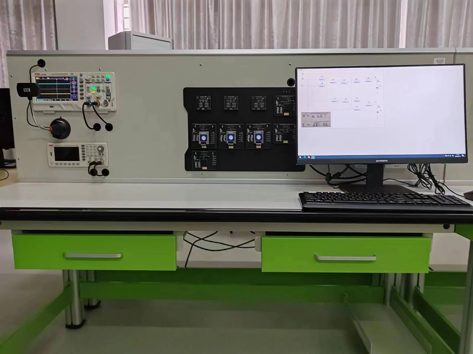
Keysight Technologies' guidance on in-circuit and functional testing describes ICT and functional testing as complementary methods rather than interchangeable solutions.
IPC standards also distinguish workmanship acceptance from other forms of verification.
IPC-A-610J, Acceptability of Electronic Assemblies, published in March 2024, establishes visual quality acceptability requirements for electronic assemblies.
Its scope does not establish complete product functional performance, nor does it provide acceptance criteria for every X-ray or cross-sectional examination.
Consequently, a PCB assembly that satisfies applicable visual workmanship requirements has not necessarily demonstrated that its power supplies, communication interfaces, control functions, and firmware operate according to the product specification.
Likewise, passing a functional test does not automatically establish that every solder joint meets the applicable workmanship acceptance criteria.
For an OEM, the useful question is which combination of inspection and testing the product actually needs, not which single method is best.
What Can Functional Testing Verify on an Assembled PCB?
The answer depends on the product design and the approved test procedure.
Consider an industrial controller PCBA containing a microcontroller, power regulation circuitry, digital inputs, communication interfaces, and output drivers.
A production functional test might verify that the board accepts its specified supply voltage, establishes the required internal power rails, boots correctly, communicates through its designated interfaces, and produces expected output responses.
If the product includes analog measurement circuits, the test may apply known input signals and compare the resulting measurements against approved limits.
If the PCB controls an external load, the test may activate the output under an appropriate test condition and measure the resulting electrical behavior.
For a communication board, the test may establish a link, exchange specified commands, or verify selected data-transfer functions.
Receiving a response from a communication interface, though, does not mean that all supported commands, speeds, error conditions, and operating modes have been verified.
The same distinction applies to power supplies.
Measuring the correct output voltage under a light load does not establish acceptable performance at every load condition, during startup transients, or across the full specified temperature range.
These examples describe possible test coverage, not a universal testing sequence that every PCBA must undergo.
The selected checks should be derived from the product's actual requirements.
Keysight's technical paper on integrating ICT and FCT describes functional testing as evaluating intended behavior through defined operating scenarios, including power consumption, communication interfaces, and overall system performance.
What matters is the relationship between the scenario being tested and the product requirement it is intended to verify.
A functional test provides evidence that the assembly produced an acceptable response under the conditions exercised by that test.
It does not automatically establish correct behavior under conditions that were never tested.
Why a PCB Can Pass Testing Even When Something Is Wrong
A test system can execute its programmed instructions correctly while still making an incorrect acceptance decision.
This distinction is examined in NI's technical documentation on Verification and Validation with TestStand.
NI illustrates the issue with a hypothetical production test measuring current consumption.
Suppose the test specification requires a device to draw no more than 500 mA. The test fixture measures current and rejects boards exceeding that limit.
Under those instructions, the test system operates correctly.
However, NI describes a possible fault in which a diode is installed in reverse, preventing part of the circuit from operating. The defective assembly consequently draws only 150 mA.
Because the test checks only whether consumption exceeds 500 mA, the abnormal board passes.
In the example, a properly designed acceptance test would also require a lower current limit. NI uses a range of 400–500 mA to illustrate the corrected approach.
The numerical limits belong to NI's example; they are not general current requirements for PCB assemblies.
This shows why pass/fail criteria require engineering justification.
An upper limit may identify excessive power consumption, but it cannot identify a missing load if unusually low consumption is also acceptable to the test program.
Similarly, a communication test that checks only whether a device responds may overlook incorrect data, timing errors, or unsupported operating conditions.
A digital output that changes state correctly without a load may still behave differently when driving the load specified for its application.
Inadequate test equipment is not usually the explanation. More often, the test specification does not cover the failure mode the equipment was intended to identify.
This is why NI distinguishes verification of a test system against its written specifications from validation that the system actually achieves its intended testing purpose.
For OEMs, a useful production test plan should therefore describe not only what will be measured, but why the selected measurement and acceptance limits are sufficient for the required manufacturing decision.
Functional Testing Must Be Designed Around the Actual Product
There is no universal FCT procedure that can verify every type of PCB assembly.
A power conversion board, a wireless communication module, and an industrial motor controller have different electrical functions and different potential failure modes.
The manufacturing test requirements should reflect those differences.
In March 2026, a member of a small mechatronics team asked the Reddit r/embedded community how hardware testing should be organized across projects. The developer wanted to understand whether a separate test firmware image was necessary and how firmware programming and hardware-in-the-loop testing could be automated.
In the public discussion, one participant described testing a board with two identical communication ports using a loopback cable and signal-generation checks.
The participant also explained that the selected method reflected the scale of the project and that a dedicated bed-of-nails fixture had not been justified for the early production batches.
This is a practitioner's self-reported experience, not independently verified manufacturing performance data.
It does show the gap between test capability and test strategy.
A dedicated fixture may allow rapid, repeatable testing of large quantities, but it introduces engineering and tooling costs.
A simpler test arrangement may be appropriate for a different production volume or product design, provided it meets the agreed verification requirements.
A loopback test can verify a defined communication path, but it does not necessarily reproduce every condition the interface will encounter in its final application.
Likewise, a board-level FCT station may simulate sensors or external equipment rather than incorporate the complete finished product.
The OEM and manufacturing team need to determine which functions can be evaluated at the PCBA stage and which require final system assembly.
This matters most for products involving mechanical actuators, wireless antennas, calibrated sensors, external power stages, or other elements whose final behavior depends on the complete device.
Functional test coverage should therefore be based on the product's requirements and manufacturing configuration, not merely on the availability of a particular tester.
Test Firmware, Production Firmware, and the Risk of Testing the Wrong Configuration
Many modern PCB assemblies cannot perform their intended functions until firmware has been installed.
This creates additional decisions during production testing.
One approach is to program dedicated test firmware that exposes diagnostic functions, drives outputs, and reports internal operating conditions.
After testing, the manufacturing process may need to replace the test firmware with the approved production firmware.
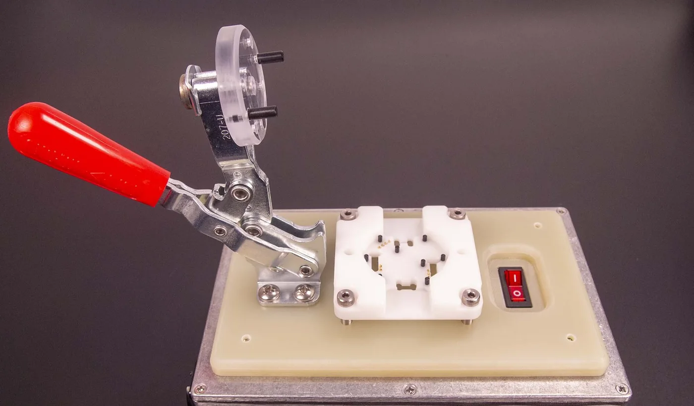
Another approach is to include a controlled diagnostic mode within the production firmware itself.
Both approaches can be appropriate, but they introduce different risks.
In a September 2025 discussion about embedded-device production testing, engineers described different practices, including dedicated test firmware, production firmware with a test mode, serial-number programming, and automated fixture-controlled test stations.
One concern raised was the possibility of a device being shipped with only the diagnostic firmware installed.
Using production firmware for testing can reduce that particular transition, but only if its diagnostic functions are sufficient for the intended verification.
Dedicated test firmware may provide better access to internal signals or hardware functions that normal application software does not expose.
It also requires control over when and how the final firmware is programmed.
The choice depends on the system architecture, testing needs, security requirements, and production workflow.
If a test is conducted using one firmware image and the board is subsequently programmed with another, the manufacturing procedure should determine whether any functions need to be verified again after final programming.
For products containing customer-specific settings, serial numbers, calibration data, or security-related provisioning, the test procedure may also need to confirm that the correct configuration has been applied.
A record stating that a PCBA passed FCT is incomplete if the result cannot be associated with the hardware and firmware configuration that was actually tested.
The Test Fixture and Program Also Need Validation
Even when the functional test procedure is technically appropriate, the test equipment can introduce its own problems.
A poorly seated connector, damaged probe, incorrect cable, unstable power supply, or faulty instrument may produce results that appear to indicate a defective PCB assembly.
The opposite can also happen if the test system incorrectly reports a pass despite not applying the intended stimulus or measuring the expected response.
For this reason, test fixture verification and maintenance are part of the overall testing arrangement.
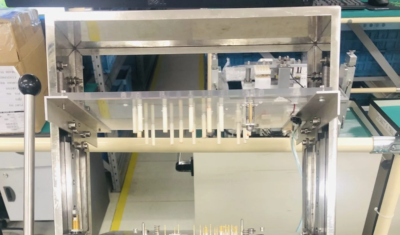
Keysight's guidance on ICT fixture integrity describes checking probe connections, wiring continuity, missing probes, and unintended shorts to confirm that the fixture itself operates as intended.
Although the document concerns ICT fixtures, the broader issue also applies to functional testing: test results depend on the reliability of the connections, instruments, and software used to execute the procedure.
The test program may additionally need confirmation against known acceptable and known defective conditions.
NI's verification and validation guidance describes the use of known product failure modes and good or bad samples to assess whether a test system can identify the defects it was designed to detect.
Such validation can reveal problems with inappropriate measurement limits, incorrect test sequencing, or insufficient failure coverage.
Changes to the fixture, instruments, firmware, or test program may require renewed assessment.
For OEMs, the practical question is whether the test setup has been demonstrated to perform the required measurements and acceptance decisions reliably for this specific product, not whether the supplier owns functional test equipment.
Why Functional Testing Does Not Replace Reliability or Product Qualification
A PCBA can pass its production functional test while still requiring further evaluation before the complete product is qualified for its intended use.
Production FCT is generally designed to confirm selected manufacturing and operating requirements within a defined testing time.
Product qualification may require testing over a wider range of temperatures, voltages, loads, mechanical conditions, or operating durations.
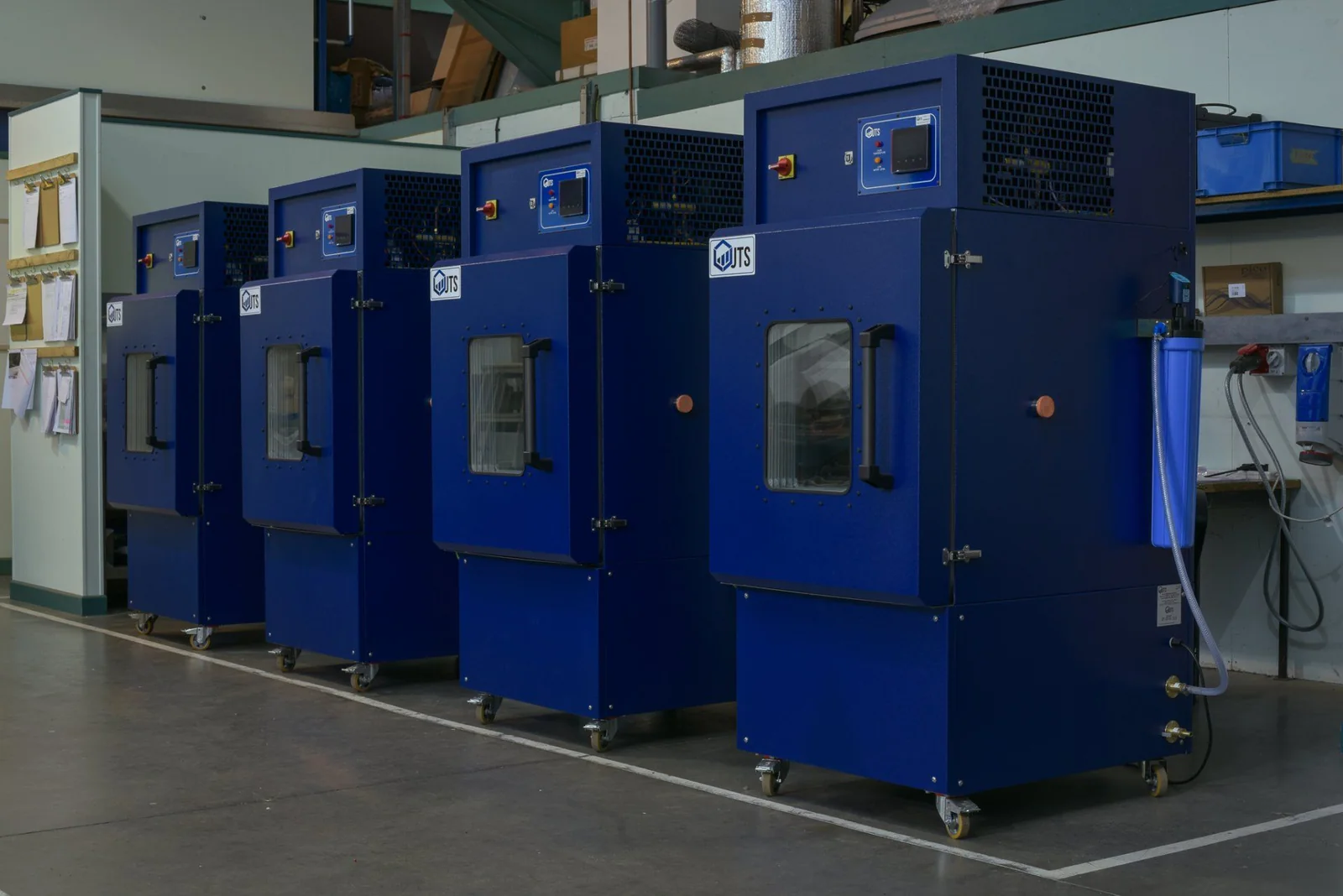
For example, a controller may communicate correctly at room temperature but require additional evaluation to establish behavior throughout its specified environmental operating range.
A power supply may meet its nominal output requirements during a short production test while still needing separate assessment of thermal performance and longer-term operating conditions.
IEC 60068-2-14:2023, Environmental Testing — Change of Temperature, provides standardized methods for evaluating the effects of specified temperature changes on test specimens.
Such environmental evaluations address questions that a conventional room-temperature functional test may not examine.
Similarly, burn-in, extended operation, environmental stress testing, safety evaluation, electromagnetic compatibility testing, and final product validation have different objectives.
Their necessity depends on the product and its applicable requirements.
A manufacturing functional test cannot be assumed to replace these activities simply because the board passed a series of electrical and firmware checks.
This matters most for OEMs developing equipment intended for industrial, medical, automotive, or other applications with specific safety, reliability, or regulatory obligations.
The final system may include cables, connectors, enclosures, cooling arrangements, mechanical loads, or external components that are absent from a PCBA-level test.
Consequently, a PCBA functional test result should be read as evidence about the defined assembly under the tested conditions, not as proof that the complete product is qualified for every intended application.
What Should an OEM Receive as Evidence of Functional Testing?
A simple PASS label confirms that a testing system reached a pass decision.
It does not necessarily explain what was tested, which requirements were applied, or whether the result corresponds to the correct product configuration.
For repeat production, quality investigations, and supplier evaluation, the supporting test record can matter as much as the final status.
At a minimum, the OEM and EMS provider should establish what information needs to be retained for the project.
Depending on the product and traceability requirements, relevant information may include the board or batch identifier, hardware revision, firmware version, applicable test procedure, measured results, acceptance limits, test date, and final disposition.
If a board fails, the record may also need to preserve the failed test step, observed measurement, diagnostic information, repair activity, and subsequent retest result.
These are not automatically mandatory fields for every commercial PCBA project.
They are examples of information that can support the evaluation and traceability of production test results.
NI's documentation on TestStand database design demonstrates how individual unit identifiers, overall results, test-step outcomes, measurement limits, and recorded values can be linked in a structured test database.
This allows the outcome for a particular assembly to be distinguished from the results of the production batch as a whole.
IPC-1782B, Standard for Manufacturing and Supply Chain Traceability of Electronic Products, also provides a risk-based framework for determining appropriate material and process traceability.
Its scope includes areas relevant to test and inspection activities, firmware programming, repair and rework, and functional test records.
The level of documentation should reflect the project's needs and the traceability requirements agreed between the customer and supplier.
A product requiring long-term field maintenance may justify more detailed test records than an application with limited traceability requirements.
For OEMs, a useful acceptance record should make it possible to identify what was tested, under which configuration, and whether the defined acceptance criteria were satisfied.
Without that context, a test result can be difficult to interpret when a later production or field issue requires investigation.
Who Decides Whether a PCBA Has Passed?
An EMS provider can execute a functional test, but the test equipment alone does not determine which product requirements should be accepted.
Those requirements must originate from an approved technical specification, agreed manufacturing procedure, or another authorized source.
For example, a manufacturer may know how to measure the voltage at a power output.
But the acceptable voltage range, permitted load, timing conditions, and response to abnormal behavior must be defined for the actual product.
The OEM may develop the test specification and provide the fixture or firmware.
Alternatively, the EMS supplier may help develop the test arrangement from the customer's product requirements.
In either case, the responsibilities for developing, validating, approving, and maintaining the test procedure should be clear before production begins.
A change to the approved hardware, firmware, or test program may also affect the validity of previously established acceptance limits.
ISO 9001:2026, Quality Management Systems — Requirements, provides a current quality management framework relevant to controlled production, product conformity, external providers, and the release of products and services.
However, conformity to a quality management system standard does not mean that every possible electronic function has been tested.
The technical coverage still depends on the approved product requirements and the actual verification activities.
For a PCBA manufacturing project, this means that the OEM and EMS provider should establish which testing operations are included, what evidence will be provided, how failures and retesting will be handled, and which conditions authorize release for shipment or further assembly.
It is also why a functional testing quotation should not be judged on the presence of the term FCT.
Two manufacturers may both offer functional testing while proposing different test sequences, fixtures, execution times, failure coverage, and reporting arrangements.
The meaningful comparison is the agreed testing scope and the evidence it produces.
A PASS Result Is Only as Meaningful as the Test Behind It
Functional testing provides a useful way of confirming that an assembled PCB performs specified operations before delivery or integration into a finished product.
But the meaning of a pass result depends on several conditions: the functions selected for evaluation, the stimuli applied, the measurements collected, the acceptance limits used, and the hardware and firmware configuration under test.
The Analog Devices engineering discussion illustrates why an unexpected electrical measurement does not necessarily establish a defective semiconductor.
NI's test-system example demonstrates the opposite risk: a defect can remain undetected when a test program is implemented correctly against incomplete acceptance criteria.
Both point to the same manufacturing principle. A test result must be interpreted in relation to what the test was designed and validated to detect.
AOI, X-ray inspection, ICT, and FCT provide different forms of evidence about PCB assembly quality. Production functional testing should be coordinated with appropriate inspection, engineering validation, and any additional product-specific requirements.
For an OEM preparing an electronic product for manufacture, the most useful starting point is a defined functional specification, applicable hardware and firmware configuration, proposed test methods, measurable acceptance criteria, and clear responsibility for approval and release.
Tongyong Industries supports PCB fabrication, component sourcing, SMT and through-hole assembly, engineering review, and PCBA testing.
Through its PCBA testing and quality control services, OEM customers can submit their functional requirements, firmware needs, available test procedures, fixtures, reference samples, and acceptance criteria for an initial manufacturing and testing review.
Clarifying the test scope before production begins helps establish what the PCBA can be verified to do, what additional evaluation may be necessary, and which evidence will support the final manufacturing acceptance decision.